Sections
Most light shows have at least one enclosure strategically place in the yard to control and power a set of props and pixels. These grey or beige boxes are the seldom noticed lifeblood of the show. This build walks through creating an enclosure that includes a single P10, P5, or even P2.5 LED matrix panel turning it into a handy “Tune to” sign or extra prop for your show.

Parts
Let’s take a look at the major parts that make up the core of this build. I’ll cover the key aspects of each and why I chose them. I’ve also include a list of the minor, optional, or suggested parts near the end of this section. If you have suggestions to improve this build, please leave a comment below.
Enclosure
The most critical component of this build was finding an enclosure, with a clear lid, that can fit a 320mm by 160mm (12.6″ x 6.3″) LED matrix panel. It was important for the enclosure to be designed for outdoor use (UV stabilized and weatherproof) so it could stand up to the elements for years.
After some searching, these requirements lead me to the BUD Industry NBF-32422 Box. The budind.com website was very helpful as they provide detailed reference drawings and measurements. This let me confirm the clear lid could accommodate the LED matrix panel before ever purchasing it. This enclosure is intended for outdoor user and is UV stabilized so being outside for months at a time won’t be a concern.
While the cost of the NBF-32422 Box is about a third more than something like the CableGuard CG-1500, I think it’s worth it for considering it can double as a prop in the show.
Add-a-Shelf
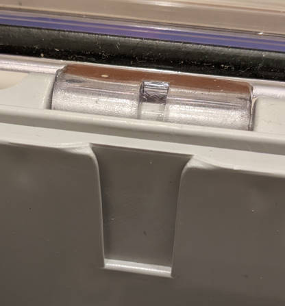
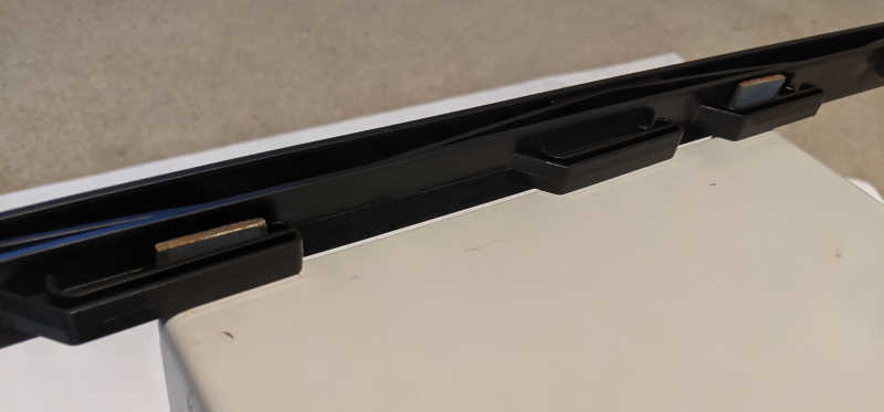
As an added bonus, the NBF-32422 Box (and other similar BUD Boxes) has a neat feature that made this build much easier and better. Near the top of the walls are four shallow trapezoidal notches for an Add-a-Shelf kit. BUD Industries refers to it as the Hinged Panel Bracket Kit and has a reference drawing for it. This works perfectly to add a black acrylic or polycarbonate sheet at the right height for both mounting the LED matrix panel and hiding the the internals. I’ll show more about using this in the step-by-step instructions below.
LED Matrix Panel
| Density | Pixels Wide | Pixels High |
|---|---|---|
| P10 | 32 | 16 |
| P5 | 64 | 32 |
| P2.5 | 128 | 64 |
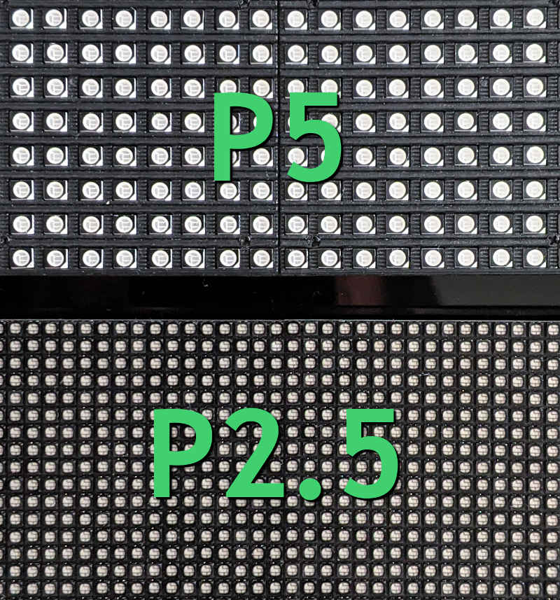
One of the most common sizes for LED matrix panels is 320mm by 160mm (about 12.6″ x 6.3″). Different pixel densities exist in this size which provide options for resolution and power consumption. My original build in 2017 used a P5 panel, which was sufficient for basic text and very simple graphics. In 2020, I upgraded to a P2.5 panel and it was like going from standard definition to HD TV. The higher density panel offered much better rendering of fonts and images looked good enough to tell what it was. In my show, the distance for the viewers on the street isn’t too far from the box, so the improved resolution was noticeable.
Another factor to consider when looking at LED matrix panels is the scan mode. This describes, in part, how much of the screen is updated or refreshed at a time. It relates to the brightness of the panel with lower scan rates generally being brighter (1/4 scan mode is brighter than a 1/8 scan mode). When selecting a controller for your panel, it is critical that the needed scan mode is supported. With the 320mm by 160mm size panels, the scan mode for a P2.5 panel is 1/32 compared to a P10 panel with a 1/8 scan mode.
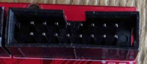
One last note on LED matrix panels: They do not work the same protocol as WS2811 or WS2813 pixels. They use a HUB75 or HUB75E interface which is why they require a different controller. The connector will look like a 2 by 8 set of pins and will connect to your controller via ribbon cable. The “E” version indicates an extra data line that is more commonly needed with higher density panels, like P2.5.
A great resource for even more information about using a P2.5 panel with the Electrodragon Pi Hat can be found at https://github.com/hzeller/rpi-rgb-led-matrix/issues/521.
Power Supply
A 5 volt (5v) power supply is needed in the enclosure to power the LED matrix panel. I used a 300+ watt power supply to ensure plenty of capacity for the panel and several strips of 5v pixels. While I’m currently using a generic power supply, I’ll switch to a Meanwell 300W 5V power supply in the future. It’s a good practice to limit the expected power used to 80% of your power supply. This allows for some overhead as power supplies can be affected by temperature.
Review the specifications for your panel and check for the max power per panel. The P2.5 panel I selected lists 32W of power consumption. If they don’t include that information, look for a maximum power per square meter. I found a maximum power consumption listed at 620W per m2. With a single panel being .32m by .16m, you get an area of .0512m2. Multiplied out, you have 31.74W per panel.
Controller
The last major component is the LED matrix panel controller. In this build, I’m using a Raspberry Pi 3 with a “hat” (Raspberry Pi Add-On board) to control the panel. This Pi will also function as an Falcon Player (FPP) remote.
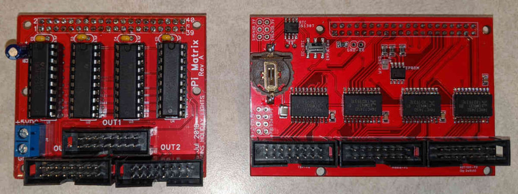
My original 2017 build used a Raspberry Pi Zero W with Ron’s Holiday Lights Raspberry Pi Matrix Adapter. This was just enough horsepower to run a P5 matrix at 25ms sequence timing. The 2020 upgrade moved to a Raspberry Pi 3 with Electrodragon’s RGB LED Matrix Panel Drive Board. This was largely driven by the P2.5 panel upgrade, with its 1/32 scan mode, and running the show at a higher frame rate with 17ms sequence timing.
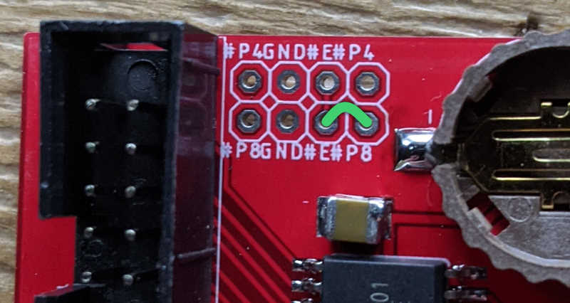
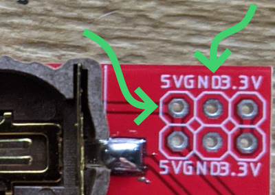
In order to enable 1/32 scan mode on the Electrodragon board, a jumper is needed from P8 to E. This connects the E line data to Pin 8 on the HUB75 interface. I recommend adding a 2 by 4 group of headers and using slip on jumpers. This allows for reconfiguring if needed in the future without the need for more soldering.
Alternatively, a controller like the OctoPlus or PocketScroller v2 from kulplights.com might be great options for P5 or P10 panels (down to 1/16 scan modes), but not for P2.5 panels which require 1/32 scan mode.
Additional Parts
To round out the build, you’ll need the following:
- Fuse Block (with Indicator LEDs)
- Ensure enough terminals to cover pigtails and controllers
- Terminal Strip with Jumpers/Forks
- Alternative – Dual Terminal Fuse Block (removes need for Terminal Strip)
- Recently upgraded to this and it works great and simplifies the number of parts
- Fuses
- Rated for 10 amps or less
- Solid Wire
- Like 14 gauge Romex
- Power Cord
- Bare wires to connect to power supply and feed through cable gland
- Pigtails (to connect to LEDs)
- I used Ray Wu style 3 Pin for power and data
- Cable Glands – Multiple sizes
- I found PG9 glands worked for my power cord and pigtails
- Opaque Black Polycarbonate Sheet
- At least 12 7/8″ by 9″
- 1/8″ thick works best
- Used with Add-a-Shelf kit for the LED matrix panel shelf
- Any type of plastic sheet
- Acrylic, Polycarbonate, ABS, etc
- For making a mounting panel for parts in bottom of the enclosure
- #10 x 1/2″ Self-Drilling Sheet Metal Screws
- For empty offsets in bottom and on back of enclosure
- M5 x 8mm Machine Screws for offsets with pre-installed inserts
- M2.5 Nylon screws, nuts, and offsets
- Other nuts and bolts for mounting
- For Fuse Block, Terminal Strip, etc
- Optional – Dielectric grease for waterproofing
- Make pigtails much easier to connect together
- Optional – SD Card Extender
- Optional – ESPixelStick for controlling 5v pixels
For mounting the box in the yard, I recommend the following:
- 1″ by 1/8″ flat stock, about 30″ long, steel or aluminum
- 4′ Step In Fence Post (2)
- 3-4′ of Rope
- Tent Stakes
The Build
With your parts gathered, I’ll walk through, step by step, assembling the enclosure.
As you build things out, make sure everything is well secured since things can move quite a bit in strong wind!
Enclosure Prep
The first step is determining a rough fit where everything will go in the bottom of the box. Find a good location for the power supply, fuse block, terminal strips, and Raspberry Pi with controller board attached. Plan out space for anything else you’re adding like a ESPixelStick controller. Keep some space between each part. The fuse block and terminal strip should sit parallel so wiring in the pigtails will be much easier. Be sure to consider keeping things clear of the WiFi antennas on the Raspberry Pi and/or ESPixelStick. I try to locate them away from the power supply just to be on the safe side.
Using the rough fit, mark where your power cable and pigtails will need to go. Using a step bit, drill 5/8″ holes where the PG9 cable glands will go. Placing them about mid-height in the enclosure provides enough room to adjust or route wires as needed. While using just a hole or a cable clamp connector will work, the cable glands do a great job of keeping the enclosure as waterproof as possible.
Power Supply
The power supply that I’m using has built in mounting holes that line up well enough with the standoffs in the enclosure. Use 4 sheet metal screws, secure the power supply and connect the power cord through the cable gland.
An alternative for mounting the power supply is to use a sheet of acrylic or polycarbonate, cut to fit the bottom of the enclosure, that can be mounted to the built in standoffs. This will also double as the mounting sheet for the other parts. Mark holes aligned with the built in standoffs and drill. As needed, drill additional holes for mounting the power supply, either for bolts or to pass cable ties around it. Once secured, check the fit, but don’t fully mount the sheet in the enclosure until after attaching the rest of the parts. You may have to hold off on attaching the power cord in this case until after the mounting sheet is complete and installed.
Power Connections
For the fuse block and terminal strip, arrange them on your mounting sheet, being careful to avoid blocking where the enclosure’s standoffs are. Mark holes and drill. If you’re using a sheet of thin material, be easy on how hard you drill, otherwise the sheet may crack. Bolt or cable tie the fuse block and terminal strip to your sheet and check the fit into the enclosure.
Using the 14 gauge wire, connect the V+ from the power supply to the fuse block and the V- to the terminal strip. Depending on your terminal strip, you may need to connect one side all together to work as a shared bus. Don’t forget to install your fuses.
Controllers
Raspberry Pi & Matrix Controller
On your mounting sheet, mark the holes for the Raspberry Pi and drill them. I recommend using M2.5 nylon offsets and nuts to minimize the risk of shorting anything. You’ll want to install the offsets and nuts first, add the Pi, then add another layer of offsets to connect the matrix controller Pi hat. Connect the matrix controller to the Pi and then finish off the stack with nylon screws on the top. If you’re using a P2.5 LED matrix panel and Electrodragon hat, don’t forget to connect the E line.
For power, both matrix controller Pi hats I’ve mentioned have 5v and GND connections which can feed power back to the Pi. Connect the fuse block side to 5v and the terminal strip to GND. Small wire will work find as it is only powering the Pi and Pi Hat. The LED panel will have its own power connection.
I recommend adding an SD card extender to the Raspberry Pi. Once the Pi is mounted, getting to the SD card on the bottom of it is a pain. The extender makes it much easier to get to the SD card without having to disassemble things. To ensure everything is secure, I used a small piece of Gorilla tape (heavy-duty duct tape) between the SD card extender and the SD card slot on the Pi.
ESPixelStick
If you’re including an ESPixelStick v3, from ForkInEye.com, it has a single hole mount. Add a hole to the sheet and put in a nylon offset and nut, then add the ESPixelStick, and finish off with a nylon screw.
Finishing the Internals
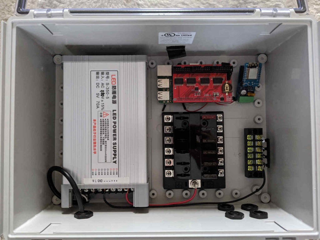
So far, you should have the power supply installed and the fuse block, terminal strip, Pi with Hat, and any additional controllers on a mounting panel ready to go into the enclosure. If needed, line up the mounting panel with the offsets in the enclosure, mark and drill, then install with screws. Double check that V+ goes from the power supply to the fuse block and V- to the terminal strip.
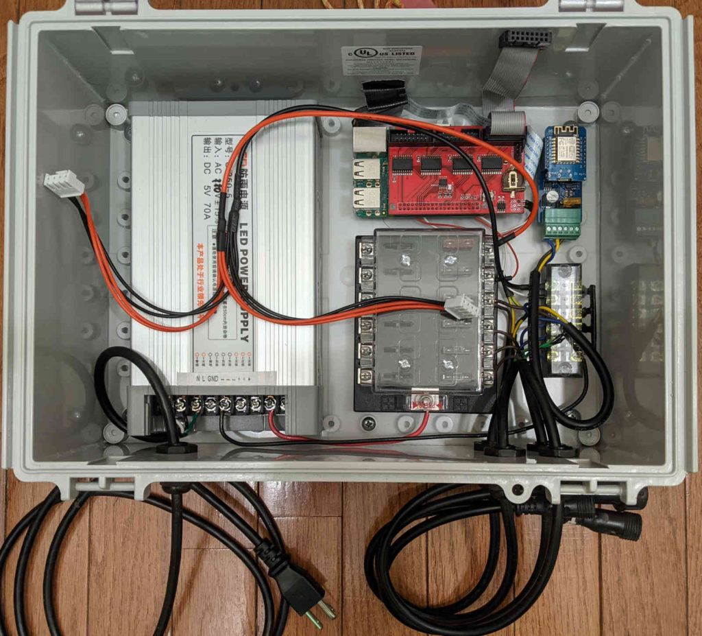
Slide the pigtails in through the cable glands. Connect the brown wires to the fuse block (V+) and connect the blue wires to the terminal strip (V-). In case you’re wondering about wire colors, check out https://www.electronicshub.org/electrical-wiring-color-codes/ for a lot of great info. If you have an ESPixelStick, wire it up and connect the data line to one of the pigtails. Be sure to mark that pigtail with white paint or a cable tie to make it easy to know which provides data when connect LEDs later without having to open the enclosure. Connect the wires from the Pi Hat, which will also power the Pi. Lastly, connect the power wires that came with the LED matrix panel to the fuse block and terminal strip.
Things should look about like this:
Add-a-Shelf
With the lower section of the enclosure ready, we’ll now focus on the LED matrix panel and the shelf that it will be mounted to.
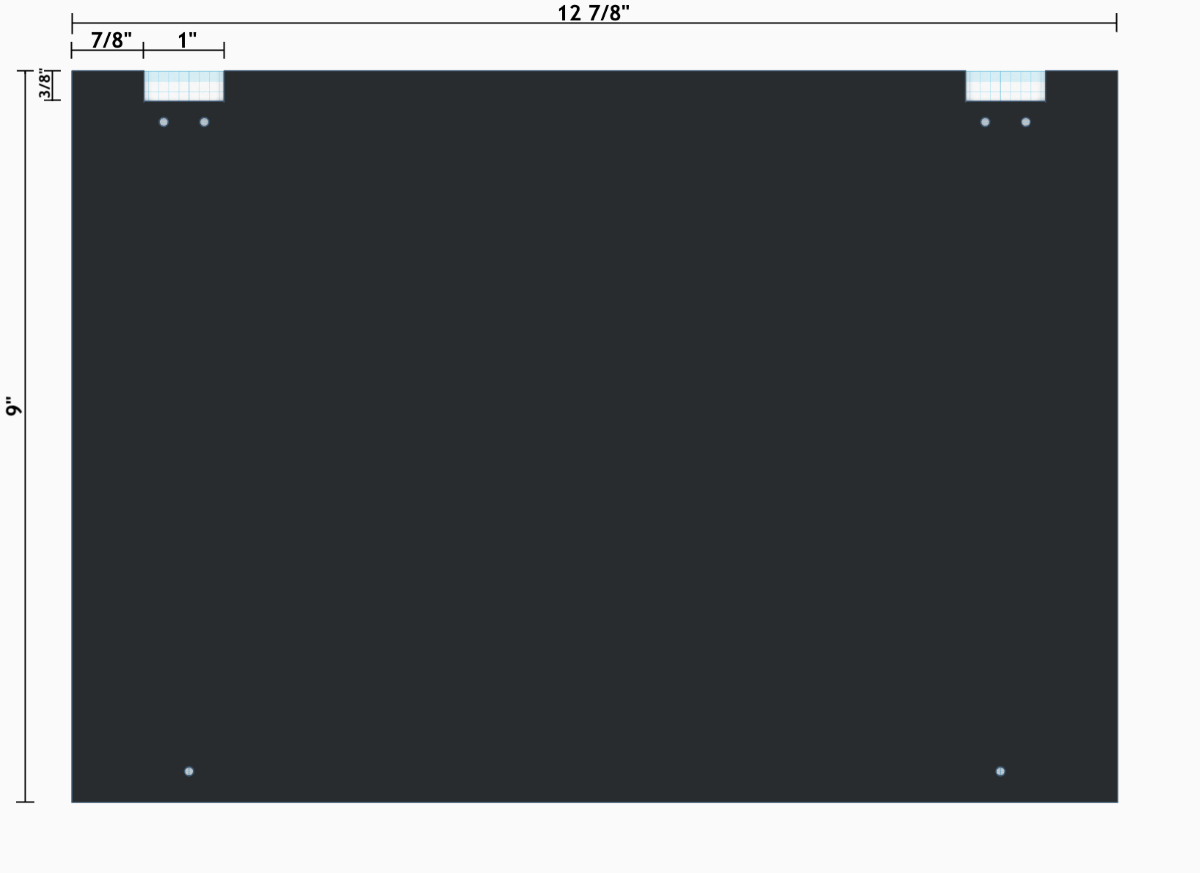
Cut your black acrylic or polycarbonate sheet down to 12 7/8″ by 9″ to fit the top of the enclosure. Two 1″ wide by 3/8″ deep notches will to be cut in the sheet for the hinge side of the Add-a-Shelf bracket. Each notch starts 7/8″ from the edge. Below is my template as an example and you can find the TinkerCAD model at https://www.tinkercad.com/users/3wnzQad3hYK-blinkygeek.
Panel Install
Measure the mounting holes for the LED Matrix Panel onto the black sheet. Be sure to leave enough room, between 1/4″ to 1/2″, around the edges to account for the taper of the lid when it closes over the panel. When installing the screws for the LED panel, add a nut to the top side of the sheet. This will prevent the screws from slipping down and provides a way to ensure the LED panel is level and at the right height.
Cut down the length of the Add-a-Shelf hardware to fit the trapezoidal slots allowing the sheet to be level. Attach the hardware to the sheet with screws.
Cut holes for the power and data cables that connect to the panel. I recommend with cutting them a bit bigger that is needed to make disconnecting them later much easier. I’m sure there is a better way to cut polycarbonate, but I used a Dremel with cut-off wheels to do most of the work, then filed the edges.
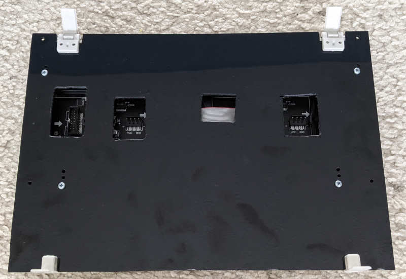
Insert the hinged add-a-shelf hardware into the slots of the enclosures and connect the power and data cables to the LED matrix panel. Gently close the shelf and slide the fixed side into the other slots. Carefully test closing the enclosure lid to make sure the LED matrix panel fits properly. Make adjustments if needed, mostly by adjusting the nuts on the panel mounting screws.
Mounting / Yard Install
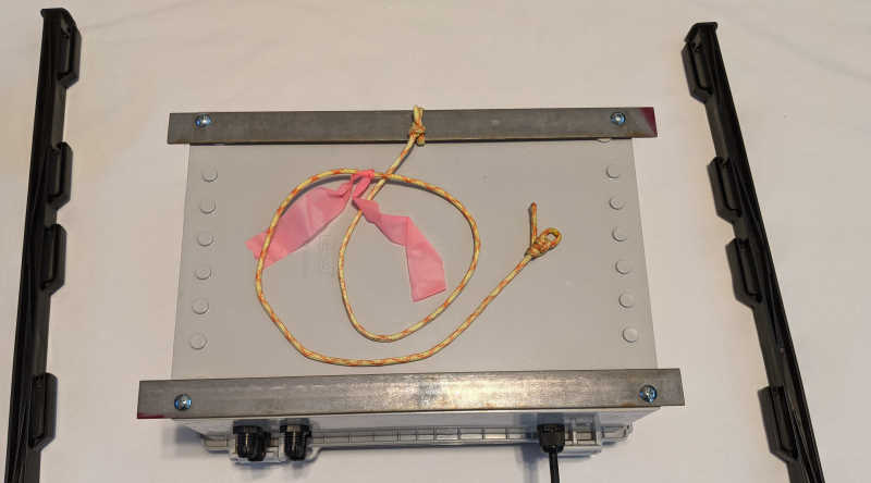
The method I came up with for mounting the box was to leverage the threaded holes on the back of the box and attach flat steel stock. I cut them longer than the box so they could slot into the poles. Add a few zip ties under the flat stock and around the poles to hold everything together.
As an option to provide a bit more protection from the weather, I used a scrap piece of the black polycarbonate to make a roof over the box. It attaches to the poles with a few cable ties and does a good job of cutting down on the sun, rain, and snow that land on the top of the box.
Software & Configuration
FPP on Pi
If you’re using a P5 (64×32) or P10 (32×16) panel, skip down to the next section to configure FPP for the LED Matrix Panel.
FPP Tweak for P2.5 Support
As of 3/9, this tweak was added to the FPP master branch and will likely be in FPP 5.0 and above. Check the LED Panel configuration to see if the option is already present. The steps below are based on FPP 4.5.1
With a P2.5 (128×64) panel, an additional configuration option has to be added to the FPP code. You’ll need to be able to SSH into your Raspberry Pi that will be attached to the LED panel. I recommend using PuTTY from https://www.chiark.greenend.org.uk/~sgtatham/putty/latest.html as an SSH client. You’ll also need to know the IP Address of your Raspberry Pi.
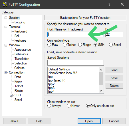
- Open PuTTY
- Enter the IP Address of your Raspberry Pi in the Host Name field
- Click Open
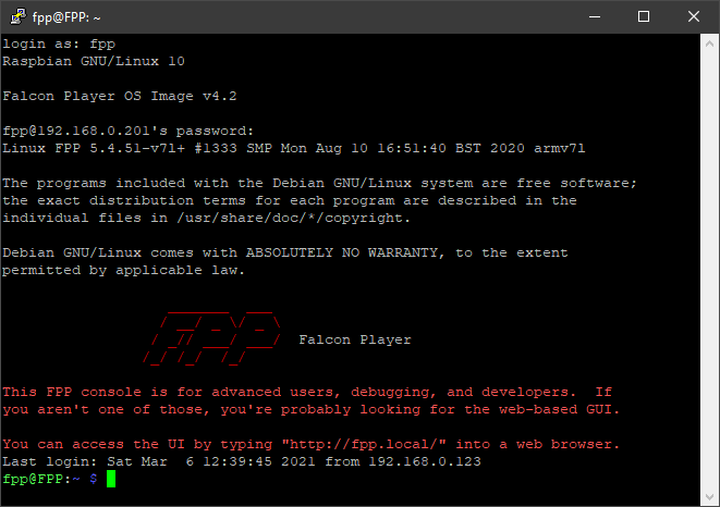
- login as:
fpp - Password is
falconby default
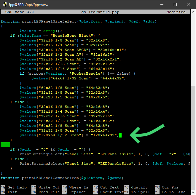
cd /opt/fpp/wwwsudo nano co-ledPanels.php- Search (Ctrl-W) for
printLEDPanelSizeSelect - Find the end of the
elseblock - Add
$values["128x64 1/32 Scan"] = "128x64x32"; - Save change and exit (Ctrl-X)
LED Panel Config on FPP
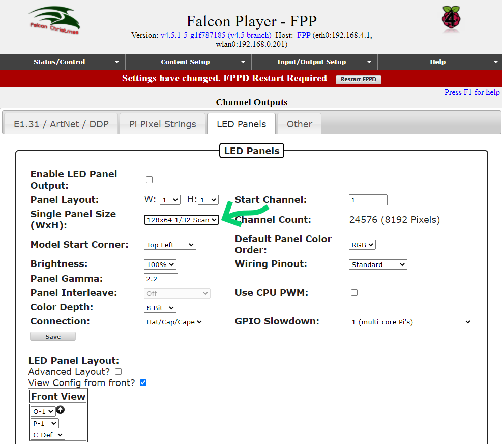
Open the FPP web console, head to Input/Output Setup then Channel Outputs. On the LED Panel tab, select the Single Panel Size for your panel making sure to select the correct Scan setting. If you make the code tweak above for a P2.5 panel, if should appear in this drop down.
Be sure to Enable LED Panel Output before trying to test. I forgot this several times! Also set your Start Channel if you know it at this point, otherwise it can be done later. Depending on the model of Raspberry Pi used, the GPIO Slowdown setting might need to be changed if the panel’s display is garbled.
Testing
With everything configured, a quick test will confirm everything is good to go. Open the FPP web console and under Status/Control, open Display Testing. Set your Start Channel and End Channel values to cover the LED Panel’s range, then Enable Test Mode. You should see a consistent pattern on the panel with no glitching.
Conclusion
With the right enclosure and an LED matrix panel, it’s great to take an otherwise behind-the-scenes part of a light show into a useful prop. In the comments below, let me know how your build went, suggestions for improvements, or other related ideas.
Parts and Pieces List
Links to parts and pieces used in this build:




6 comments